Finite element analysis – predicting the real world
When designing products and components, it is vital to ensure their structural integrity and reliability under expected real-world conditions.
Finite Element Analysis (FEA) is a critical part of modern product development. It allows designers to digitally simulate how structures will respond to stresses, strains, heat and dynamic forces.
At Cambridge Design Technology, we integrate FEA with physical prototyping to enhance precision, accelerate timelines and reduce project costs.
Why is FEA used?
When mechanical designing a product or component, FEA is vital for predicting how a 3D CAD model will behave under real-world conditions.
Commonly simulated effects include:
- Repeated impact or dynamic loading
- Strain from sudden or prolonged forces
- Thermal variations
- Vibration and fatigue cycles
- Pressure or fluid interactions
FEA is the only way to reveal how a part might fracture, bend, deform, overheat, or wear out. It will also demonstrate that it will perform as intended.
Modern developments, such as integration with digital twin systems, now allow simulations to be updated dynamically with real-world usage data, further enhancing predictive accuracy.
Benefits of FEA
For engineers, project managers, and product development leaders, FEA offers powerful advantages:
Early Risk Identification
By validating designs during the CAD phase, potential flaws in materials or geometry can be detected early — avoiding costly iterations at the prototyping or manufacturing stages.
Reduced Development Time
FEA significantly cuts down on the number of prototypes needed, helping to accelerate the design-to-manufacture cycle and deliver products to market faster.
Design Optimisation
Through FEA, parts can be optimised for strength, weight reduction, thermal efficiency, or durability — often leading to significant improvements in product performance and sustainability.
Cost Savings
Reducing prototyping, minimising material use, and avoiding late-stage redesigns all contribute to lower overall development costs.
Enhanced Confidence
Accurately simulating real-world stresses is vital to ensure products meet safety standards, functional requirements and lifecycle expectations.
Modern FEA tools support sustainability efforts by enabling engineers to create durable and reliable designs that use fewer resources.
FEA applications
FEA is indispensable across industries where product integrity and performance are critical.
Common Use Cases
- Structural integrity and lifetime durability
- Fracture and fatigue testing
- Pressure and loading analysis
- Vibration and shock impact simulations
- Thermal management under operating conditions
- Fluid dynamics and airflow modelling
- Drop and impact testing
Industries Served
FEA is the go-to solution for safety, compliance and performance in aerospace, automotive, marine, sporting goods, consumer products, medical devices and industrial sectors.
With the growing adoption of Industry 4.0 and IoT technologies, FEA is a clear leader in predictive maintenance and real-time optimisation through digital twin integration.
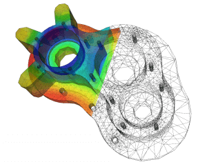
How Does FEA work?
FEA divides a solid object into thousands (or millions) of smaller elements — always tetrahedrons or hexahedrons.
Mathematical equations predict how each element reacts to physical forces, temperature changes, or fluid flows.
These element-level results are then assembled to simulate the performance of the entire part under the specified loading conditions, giving engineers deep insight into critical areas.

Linear and non-linear FEA explained
All materials have limits on the stresses and deformations they can withstand.
Using a simple example of a plastic ruler:
Linear FEA models the elastic phase, where bending within a limit allows the ruler to return to its original shape once the force is removed.
Nonlinear FEA models plastic deformation, where excessive force leads to permanent bending or fracture.
It is clear that if the stress exceeds the yield strength of the material, permanent damage will occur.
FEA is vital for designers. It ensures products remain safely within their elastic limits during normal use and accurately predicts product behaviour under extreme conditions.
Steady-state analysis is the ideal method for predicting material behaviour under prolonged or extreme loads, regardless of specific time frames. It is the perfect solution for long-term durability simulations.
Cambridge Design Technology and FEA
At CDT, we use advanced tools including PTC Creo Simulate and SolidWorks Simulation to perform detailed FEA studies, covering:
- Linear static and thermal analysis
- Nonlinear analysis for complex behaviours
- Computational Fluid Dynamics (CFD) for airflow and fluid simulation
We apply FEA to boost confidence in two critical areas:
- Design Validation
We rigorously simulate real-world loads during the design phase to verify robustness and minimise prototyping risks — saving time and reducing costs.
- Factor of Safety
We design with conservative safety margins, typically aiming for a 10x factor of safety relative to material limits.
This guarantees that peak stresses remain well below critical thresholds, enhancing product durability and customer trust.
CDT has decades of experience in product design and engineering consultancy. We understand the challenges of balancing cost, speed, efficiency, weight, size, durability, and safety.
We also fully support full documentation for regulatory compliance, quality assurance, and certification needs.
Contact our expert and friendly team of product design and development specialists for guidance and support on your current or future project.